

Project Description
CFD analysis of an engine cooling radiator
The thermal engines, particularly in the automotive sector, are temperature-controlled by a coolant circuit which carries the calories between the engine casing and the environment via a cooling radiator. The forward movement of the vehicle as well as the motor-fan unit circulate the outside air around the tubes and spacers that make up the radiator. The space under the hood imposes particular shapes on the inlet and outlet manifolds which supply the tubes of the radiator, which can be detrimental to the proper supply of each of the tubes. We propose here, by means of the numerical simulation in fluid mechanics and thermal (CFD Computational Fluid Dynamics) to analyze the supply of the tubes of the radiator.

Boundary conditions and physics models
- A flow of coolant is imposed at the inlet.
- A pressure condition is imposed at the output
- Since the target is the homogeneity of the water supply to each of the tubes, thermal analysis does not have a preponderant importance in this analysis. However, we model it in a simplified way to represent the variation of the physical properties (density, viscosity) of the coolant with the temperature which has an influence on the head losses in the tubes. A temperature condition is therefore imposed at the inlet and convective heat exchange is imposed on the wall of the tubes (in W / m2.K). The condition of “remote” temperature of the outside air is also fixed.
Simulation results
The temperature profile on the radiator walls shows an identical decrease in temperature on all the tubes between the inlet and outlet manifolds. This suggests, on the whole, a homogeneous supply of the tubes. An area is observed on the tubes where the temperature is lower in the axis of the inlet / outlet pipes. Indeed, the circulation in the tubes in question has velocity separations, and an accelerated flow opposite the inlet pipe. The heat exchange rate on the hot side in this zone is therefore less efficient and the heat exchange on the outside (cold side) side has an increased relative importance compared to the rest of the tubes. As a result, the temperature decreases.
![Velocities [m/s] on a plane in the middle of the tubes row of the radiator](https://numairo.fr/wp-content/uploads/2017/01/p10_radiateur_vitesses-plan-cfd-1024x708.jpg)
![Temperatures on the walls on the radiator [°C]](https://numairo.fr/wp-content/uploads/2017/01/p10_radiateur_temperature-paroi-cfd-1024x761.jpg)
![Temperatures [° C] in a plane intersecting a tube located in the middle of the row of tubes on the radiator](https://numairo.fr/wp-content/uploads/2017/01/p10_radiateur_temperature-plan1-cfd-1024x698.jpg)
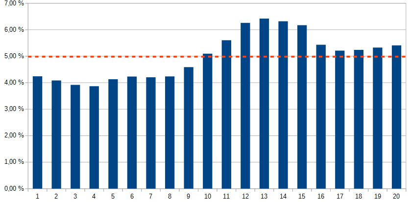
The calculation provides the flow per tube, the results are illustrated below.
![Velocities [m/s] in the section of the tubes](https://numairo.fr/wp-content/uploads/2017/01/p10_radiateur_vitesse_tube-cfd-1024x839.jpg)
Below are the current lines in order to understand the mechanism of the flow to facilitate the understanding of the origin of the imbalance in the context of an optimization.
![Pathlines colored by their velocities [m/s]](https://numairo.fr/wp-content/uploads/2017/01/p10_radiateur_ecoulement-pathlines-cfd-1024x472.jpg)
Continuation of the CFD study
Thermal performance of the radiator
The CFD Computational Fluid Dynamics allows if the question is asked to characterize and optimize the thermal performance of the device. The tubes of the radiator are fine (about 2 mm of cross section) and between the tubes, the air passes through “spacers” equipped with “openings”, very fine openings, which make it possible to increase the coefficient d exchanged to the lateral surface of the tubes.

It is not reasonably possible to mesh (see the steps of the CFD simulation) and then calculate a complete radiator with its tubes, spacers and gills. On the other hand, the study of the thermal performance of an interlayer can be carried out. These microscopic data can then lead to the definition of a macroscopic exchange law which would allow for example to resume the work carried out here and to include the mesh of the outside air and why not of the motor-fan group to go more on the determination of the performance of the device.
Thermal choc phenomenon
There is an operating temperature for which the motor has an optimal efficiency. The radiator keeps the temperature at this level. However at start-up, the engine is cold. The thermostat which controls the circulation of the coolant in the radiator remains closed until the temperature reaches the set point temperature (between 80 and 100°C) so that the motor shows rapid temperature.
At this time, the radiator changes from an ambient temperature (which may be negative in winter) to 80°C in a few seconds and in a more or less heterogeneous way (disparity between the tubes as we have seen in this study , but also the temperature difference between the inlet and the outlet of the tubes and finally between the tubes and any more massive parts.)
The hot parts expand and this differential expansion creates thermomechanical stresses. This is called thermal shock. From a numerical point of view, it is possible to follow the rise in temperature of the apparatus over time and throughout this ascent to carry out calculations in structural mechanics (FEA Finite Element Analysis) to determine thermo-mechanical stresses.