Project Description
CFD study of droplets evaporation in a cooling tower
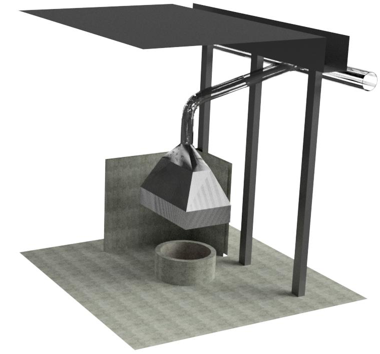
Industrial processes using hot flue gases (more than 300°C) from boilers (cement plants, steel mills, incinerators, foundries, etc.) are likely to integrate in their lines facilities to treat these smokes (NOx, particles …). However, these processors must operate at a controlled temperature, to optimize the reaction, or simply to avoid damage to the components of the devices.
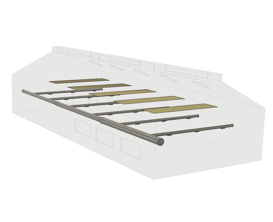
One way to control the temperature of such flows is the spraying of water droplets. The calorific capacity of the water and especially its latent heat of evaporation makes it possible to trap the heat of the smokes and to reduce the temperature. This process is carried out by the cooling towers. Changes in flow direction (elbows), contraction of the flow during cooling are causes of flow imbalance. However, this process operates optimally and controlled if the smoke flow is balanced.
Numerical simulation in fluid mechanics and thermics (CFD Computational Fluid Dynamics) makes it possible to test solutions of flow straightening taking into account the thermal effects due to the evaporation of the water sprayed. The trajectories of the water droplets can be followed until they evaporate so as to verify that they do not touch the walls before evaporation and may cause clogging due to an accumulation of dust sticky by moisture ..

Boundary conditions and physical models
- A flow is imposed as input
- A pressure condition is imposed at the output
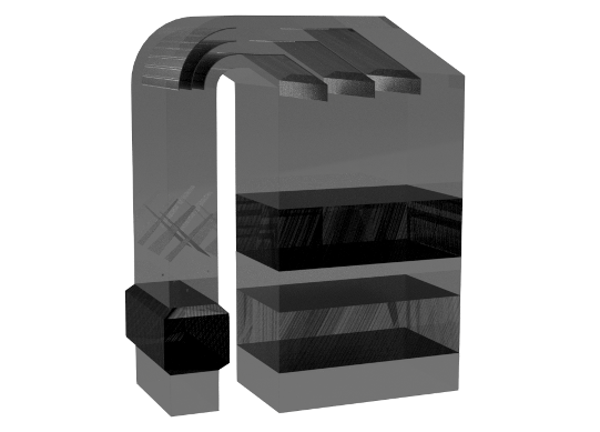
- Only one half of the geometry is modeled (condition of symmetry)
- Turbulence is modeled
- A water flow in the form of droplets whose size and injection characteristics are give
- The properties of the fumes depend on the temperature and their composition.
- Evaporation of droplets is permitted
- The evaporated water evacuates into the fumes in the form of water vapor.
Simulation results
![Velocities in the symmetry plane [m/s]](https://numairo.fr/wp-content/uploads/2017/01/P09_cool_vit-sym.png)
![Pathlines colored by velocities [m/s]](https://numairo.fr/wp-content/uploads/2017/01/P09_cool_path-vit.png)
![Temperatures in the symmetry plane [°C]](https://numairo.fr/wp-content/uploads/2017/01/P09_cool_t-sym.png)
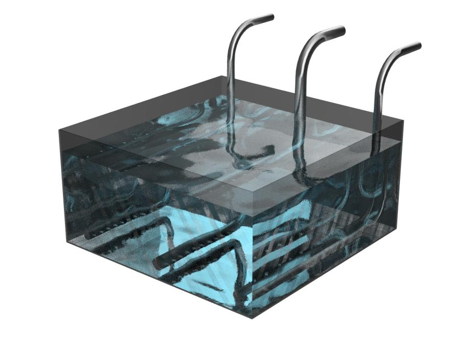
![Droplets trajectories form their spray untill their evaporation. Colored by the time from their spray [s]](https://numairo.fr/wp-content/uploads/2017/01/p09_traj-goutte-age.png)
In spite of the presence of the deflector plates, the velocity profile has an accelerated flow on the extrados of the elbow at the top of the cooling tower. One of the spray nozzles of water droplets is located in this accelerated stream and the droplets which issue therein rapidly rejoin the outlet pipe. While the other nozzle is located on the underside in a low-powered area where the water droplets are stationary for a long time or even up the tower.
The risk of this kind of situation is, on the one hand, to recover non-evaporated droplets at the outlet of the installation (one of the droplets traced, chosen statistically, emerges from the apparatus) and, on the other hand, accumulation of dust moistened by droplets become possible.
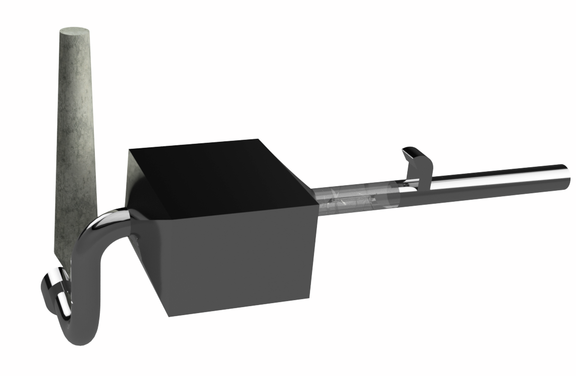
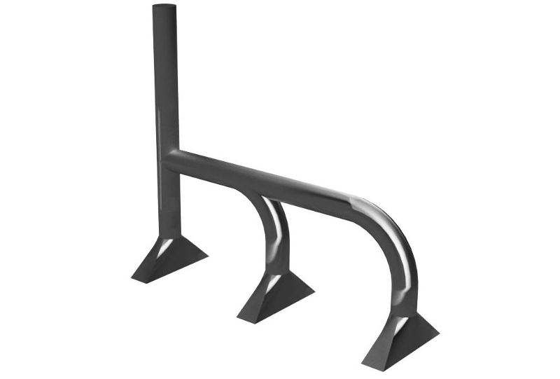
An optimization solution would be the elongation of the vertical part of the deflector plates or the use of a distribution grid beneath these plates upstream of the water injections. It is this last solution which is tested later.
![Steam concentration in the symmetry plane [Kgsteam/Kgsmokes]](https://numairo.fr/wp-content/uploads/2017/01/p09_cool_vapeur-sym.png)
Influence of the homogeneization perforated plate
The use of a grid, which is nothing other than a perforated plate, makes it possible to create pressure losses in the flow. Load losses are highly dependent on speed. The languages of accelerated flows are therefore imposed a greater resistance to the flow than in zones of low speed. Overall, the flow is therefore better distributed in the passage section. Numerically, the grid is replaced by a homogeneous medium imposing equivalent losses of loads.
Homogenization is indeed observed on the proposed example. The zero or even recirculating flow loop is suppressed and the droplets issuing from the two nozzles are entrained in the flow in the same way.
![Trajectories of droplets from theri spray untill their evaporation. Colored by he time since their spray [s] - with grid](https://numairo.fr/wp-content/uploads/2017/01/p09_traj-goutte-age-grille-cfd.png)
![Velocities in the symmetry plane - with homogeneization perforated plate [m/s] - avec grille de répartition](https://numairo.fr/wp-content/uploads/2017/01/P09_cool_vitesse-sym-grille-cfd.png)
with homogeneization perforated plate
![Pathlines colored by velocities [m/s] with homogeneous perforated plane](https://numairo.fr/wp-content/uploads/2017/01/P09_cool_lignes-de-courant-vitesse-grille-cfd.png)