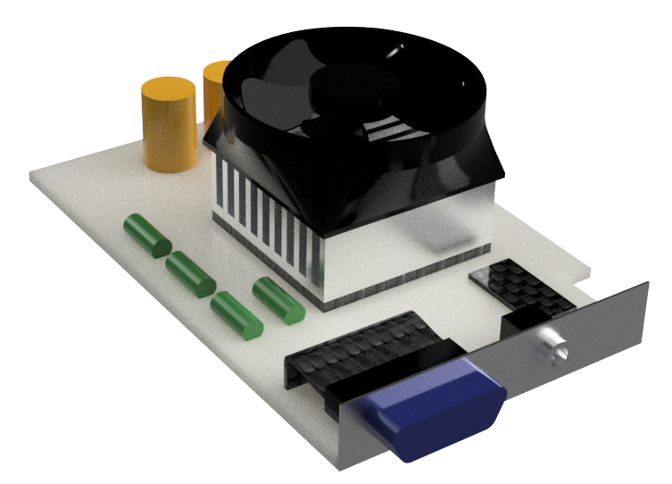
Project Description
Electrical heart – CFD Thermal analysis – Joule effect
The electrical heart of a device allows the electrical energy to be distributed in the various equipment of the device. This terminology is used in particular in the aerospace sector.
The present electrical core is subjected to a potential difference between two of its terminals. The aim of the analysis proposed here is to determine the temperature which balances on the various components crossed by the electric current under the Joule effect using the numerical simulation tool in fluid and thermal mechanics (CFD Computational Fluid Dynamics). A thermo-electric coupling is solved. Other components have a heat dissipation.
Cooling is ensured by natural convection but also and above all by radiation. Indeed, this type of apparatus must be able to operate under a rarefied atmosphere, leading to less convection. The radiation becomes then the main heat exchange which will ensure the thermal regulation.

Boundary conditions and physical models
- A thermal power (power density in W / m3) is imposed on the components concerned.
- A continuous potential difference is imposed between two terminals. The current flow as well as the joule effect are solved.
- The electrical core is located in ambient air at 20 ° C and at atmospheric pressure
- Thermal exchanges between the air and the various components are done by natural convection. Air dilatation and terrestrial gravitational force are taken into account in CFD Computational Fluid Dynamics.
- Radiation heat exchange is taken into account.
Simulation results
The stress of the electrical core is a potential difference. The level of potential as well as the current density are observable especially the circuit concerned. The temperature in the “busbars” (aluminum or copper electrical piping) remains at an acceptable level. The fuse shows a high temperature level. It must “melt” before the degradation of the elements it protects. The article Effets thermomécaniques sur un fusible presents a study devoted to it.
![Temperatures profile on components [°C]](https://numairo.fr/wp-content/uploads/2017/03/P04_coeur-electrique_Temperature-cfd.png)
![Electrical potentiel - Electric heart [V]](https://numairo.fr/wp-content/uploads/2017/03/P04_coeur-electrique_tension-cfd.png)
![Current density [A/m2]](https://numairo.fr/wp-content/uploads/2017/01/P04_coeur-electrique_flux-electrique-cfd-1024x817.png)
Coolin mechanism
The three modes of heat transfer are modeled in the CFD Computational Fluid Dynamics simulation to allow the cooling of the heating elements
- Conduction : The thermal conductivity of the “busbars” ensures a dispersion of the heat over a larger surface exposed to convection and radiation
- Convection : In contact with hot parts, the air expands and rises. The lower and upper openings on the electric core create a fresh air change.
- Radiation : Each component of the device radiates on the other components in all directions and receives radiation from other components. This exchange results in a net flow which balances the two facing surface elements. Its intensity depends on the emissivity of the surface of the component but also and especially its temperature. In the aforementioned situation of a rarefied atmosphere and / or absence of gravitational fields, this mode of thermal transfer becomes the predominant phenomenon.
![Pressures on the walls of the device [Pa]](https://numairo.fr/wp-content/uploads/2017/01/P04_coeur-electrique_Pression-cfd.png)
![Velocities [m/s] around components colored by their temperature [°C]](https://numairo.fr/wp-content/uploads/2017/01/P04_coeur-electrique_vitesse-cfd.png)
![Pathlines colored by their temperatures and temperatures on the components [°C]](https://numairo.fr/wp-content/uploads/2017/01/P04_coeur-electrique_path-cfd-1024x845.png)
![Radiating incident flux [W/m2]](https://numairo.fr/wp-content/uploads/2017/01/P04_coeur-electrique_Incident-Rayonnement-cfd.png)