Project Description
Thermomechanical analysis of a fuse – Joule effect
Within an electrical device (example of the electrical heart), the fuse is supposed to “melt” when the electrical current reaches the nominal value. At this current value, the current density in the section restriction becomes such that the joule effect creates a heating up to the melting temperature of the material composing it. The heat produced is very punctual and decreases very rapidly as one moves away from the restriction zone. These temperature variations within the conductive zone of the fuse lead to differential expansion and therefore to the appearance of thermomechanical stresses.
In this study, we propose to model using the numerical simulation tool (CFD Computational Fluid Dynamics) and (FEA Finite Element Analysis) these phenomena, the solicitation by application of a difference of potential until the deformation and the level of thermomechanical stresses are determined.

Boundary conditions and physical models of the thermal study
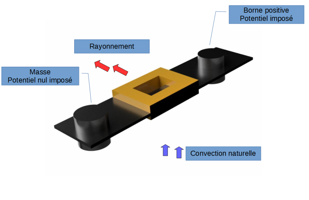
- A continuous potential difference is imposed between the two terminals. The current flow as well as the joule effect are solved.
- The fuse is located in ambient air at 20 ° C and at atmospheric pressure
- Thermal exchanges between the air and the materials composing the fuse (conductor and insulation) are done by natural convection. The expansion of air and the gravitational force of the Earth are taken into account in the modeling.
- Radiation heat exchange is taken into account.
Simulation results of the thermal study
The maximum dissipation in the model is reached in the section restriction, where the current density is the largest. The phenomena of dispersion in the environment of the emitted heat (natural convection, radiation) are balanced towards the stationary temperature field shown here.
![Profil de température de l'air dans un plan médian du fusible [°C]](https://numairo.fr/wp-content/uploads/2017/01/P04_fusible_temperature-air-cfd.png)
![Electrical potential on the fuse [V]](https://numairo.fr/wp-content/uploads/2017/01/P04_fusible-tension-cfd-1024x695.png)
![Temperature on the fuse [°C]](https://numairo.fr/wp-content/uploads/2017/01/P04_fusible_Temperature-cfd-1024x722.png)

Boundary conditions and physical models of the mechanical study
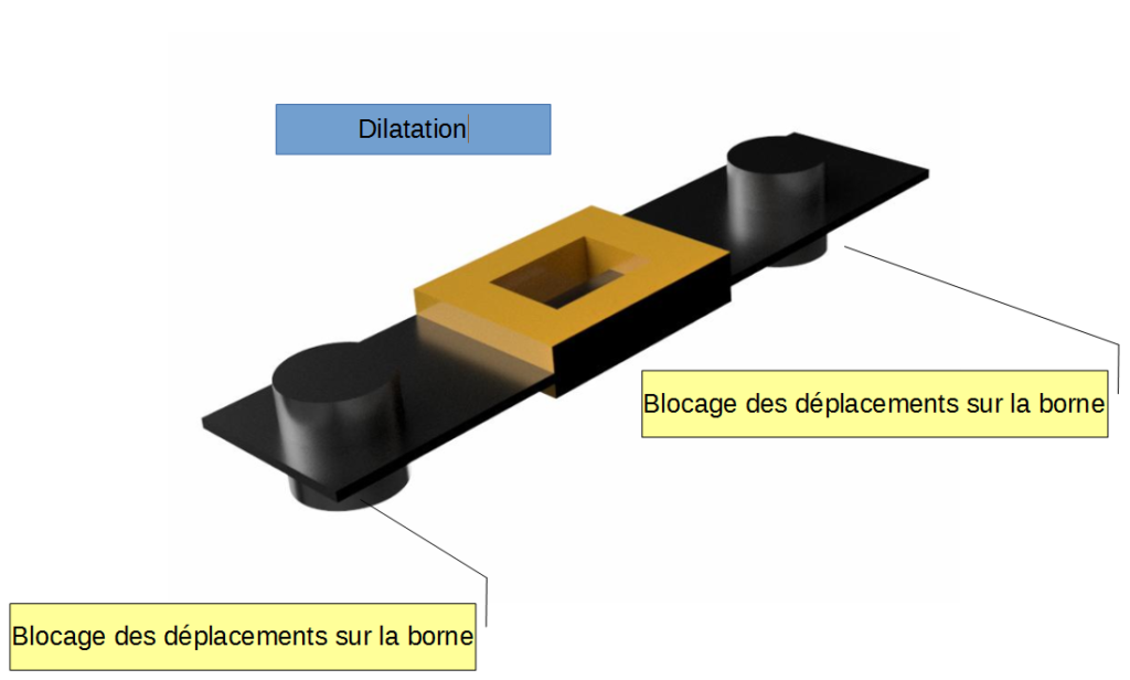
- Movements are not permitted on the fuse terminals
- The thermal expansion is modeled using the thermal profile of the thermal study
- The simulation is static linear with the hypothesis of small displacements
Thermomechanical simulation results
Peaks of non-physical constraints on the boundaries due to the very restrictive boundary condition of the displacements on these zones. The central zone which heats strong expands with the greatest amplitude. The mechanical stresses are the strongest in this zone. The level of the stresses found exceeds the elastic limit of the material, which is due to the linear character of the stress-strain relationship used here and which amplifies the deformed non-physically. An elastoplastic calculation could provide information on the actual deformation of the component.
![Von Mises constraints on the deformed shape (displacements increased 100 times) [MPa]](https://numairo.fr/wp-content/uploads/2017/01/P04_fusible_von-mises-fem-cfd-1024x657.png)
![Temperature loading on the distorted geometry (displacements increased 100 times) [°C]](https://numairo.fr/wp-content/uploads/2017/01/P04_fusible_temperature-2-cfd.png)
![Displacements on the deformed shape(displacements increased 100 times) [μm]](https://numairo.fr/wp-content/uploads/2017/01/P04_fusible_deplacements-cfd-1024x705.png)


